Plate Couplings Engineering Drawing
Plate couplings stand as core components in mechanical power transmission systems, serving to connect two rotating shafts, transfer torque efficiently, and compensate for minor axial, radial, and angular misalignments between shafts without compromising operational stability. Unlike rigid couplings that demand perfect shaft alignment and offer no tolerance for positional deviations, plate couplings rely on the elastic deformation of thin metal plate groups to absorb misalignment errors, making them widely applicable in diverse industrial machinery ranging from pumps and fans to compressors, gearboxes, and high-speed rotating equipment. Engineering drawing is the foundational technical document for designing, manufacturing, inspecting, and assembling plate couplings; it transforms abstract design concepts into visual, measurable, and executable technical information, ensuring every part and assembly meets functional and performance requirements. A precise, standardized plate coupling engineering drawing eliminates ambiguity in production, reduces processing errors, streamlines assembly workflows, and lays the groundwork for reliable long-term operation of the entire transmission system.
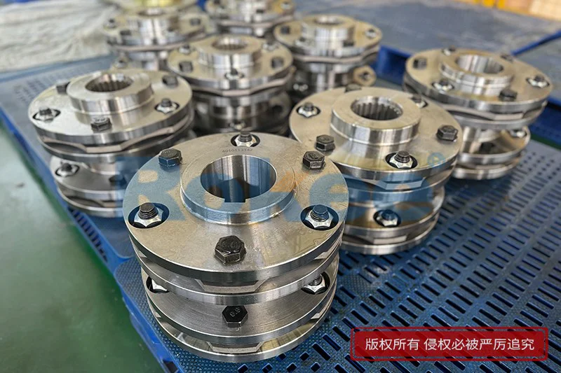
To understand plate couplings engineering drawing thoroughly, it is essential to first grasp the basic structural composition of plate couplings, as the drawing must accurately reflect every structural feature and assembly relationship. A typical plate coupling mainly consists of two half-coupling hubs, a set of flexible metal plates (diaphragm groups), high-strength fastening bolts, and auxiliary parts such as washers and spacers in some configurations. The half-coupling hubs are the connecting ends that match with the driving and driven shafts, usually featuring a cylindrical bore with keyways or tapered bores for tight shaft fitting, and a flange end for connecting the flexible plate group. The flexible plate group is the core functional part, composed of multiple layers of thin high-strength alloy steel plates stacked together; these plates are designed with uniform contour and precise hole positions, enabling elastic deformation under load to accommodate shaft misalignment while transmitting torque steadily. Fastening bolts play a dual role: they clamp the flexible plate group between the two half-coupling flanges firmly and ensure synchronous rotation of the entire coupling assembly. Each structural part has unique geometric features and functional requirements, which directly determine the expression mode, dimensioning logic, and technical annotation content of the engineering drawing. For example, the flexible plate group requires detailed depiction of hole pitch, plate thickness, outer diameter, and inner diameter, while the half-coupling hubs need clear representation of bore size, keyway dimensions, flange thickness, and bolt hole distribution.
Standardization is the primary principle guiding plate couplings engineering drawing, as compliance with universal mechanical drawing norms ensures the document is universally understandable and operable across design, manufacturing, and inspection teams. All drawing elements, including view layout, line types, dimensioning methods, surface roughness symbols, geometric tolerance markings, and material notations, must align with established mechanical engineering drawing standards to avoid misinterpretation. In terms of view selection, plate couplings are axisymmetric rotating parts, so the engineering drawing usually adopts a combination of sectional view and basic view to achieve clear and concise expression. The main view is typically drawn along the axial direction of the coupling, using a full sectional view or half sectional view to reveal the internal structure, such as the bore, keyway, bolt hole penetration, and the assembly relationship between the flexible plate group and half-coupling hubs. This view focuses on displaying axial dimensions, radial dimensions, and the relative position of each component. Auxiliary views, such as cross-sectional views perpendicular to the axis or detailed views of local key parts, are added to present features that cannot be fully shown in the main view, like the distribution shape of bolt holes on the flange, the contour of the flexible plates, and the structural details of keyways. For complex plate coupling designs with intermediate shafts or multi-stage plate groups, additional detailed views or enlarged sections are necessary to highlight local structures, ensuring no structural feature is overlooked or ambiguously represented.
Dimensioning is a critical part of plate couplings engineering drawing, as accurate and complete dimensions are the basis for ensuring the coupling’s fit, function, and interchangeability. Dimensioning for plate couplings follows the principles of completeness, rationality, clarity, and non-repetition, covering overall dimensions, functional dimensions, fit dimensions, and processing dimensions. Overall dimensions include the total axial length of the coupling and the maximum outer diameter, providing a macroscopic understanding of the component’s size. Functional dimensions are directly related to the coupling’s performance, such as the bore diameter of the half-coupling hubs (which must match the shaft diameter of the connected equipment), the thickness and number of flexible metal plates, the pitch circle diameter of bolt holes, and the diameter of bolt holes; these dimensions determine torque transmission capacity, misalignment compensation performance, and assembly compatibility. Fit dimensions involve the matching tolerances between mating parts, such as the fit between the half-coupling bore and the shaft, the fit between bolts and bolt holes, and the stacking fit of flexible plates; these dimensions are marked with corresponding tolerance grades to ensure proper assembly tightness and operational flexibility. Processing dimensions are set to meet machining process requirements, including fillet radii, chamfer sizes, groove depths, and surface machining allowances, which guide the actual processing operation and ensure the feasibility of manufacturing. When dimensioning, dimensions should be arranged neatly, avoiding crossing dimension lines, and key functional dimensions should be placed prominently to facilitate quick identification by processing and inspection personnel. Additionally, dimensioning must avoid closed dimension chains to prevent cumulative errors from affecting the coupling’s dimensional accuracy and assembly performance.
Technical requirements annotation in plate couplings engineering drawing covers surface roughness, geometric tolerances, material specifications, heat treatment requirements, and assembly norms, all of which are indispensable for guaranteeing the product’s quality and performance. Surface roughness markings specify the machining smoothness of key surfaces, such as the half-coupling bore surface, keyway side surfaces, flange contact surfaces, and flexible plate surfaces; appropriate surface roughness values are set based on functional needs, with mating surfaces requiring higher smoothness to reduce friction, wear, and stress concentration, while non-mating surfaces can adopt relatively lower roughness requirements to balance processing efficiency and cost. Geometric tolerances are crucial for ensuring the coupling’s assembly accuracy and operational stability, including cylindricity of the bore, perpendicularity of the flange end face to the axial centerline, coaxiality of the two half-coupling hubs, flatness of the flexible plates, and position tolerance of bolt holes. These tolerances restrict shape and position deviations of parts, preventing issues like uneven stress distribution, abnormal vibration, and premature wear caused by excessive geometric errors during operation. Material specifications clearly state the material grade of each component: half-coupling hubs are usually made of high-quality carbon structural steel or alloy structural steel with good strength and toughness, flexible metal plates are made of thin alloy steel with excellent elasticity and fatigue resistance, and fastening bolts are made of high-strength alloy steel to withstand clamping force and torque. Heat treatment requirements are marked for key components, such as quenching and tempering for half-coupling hubs to improve comprehensive mechanical properties, and surface hardening for bolt holes and contact surfaces to enhance wear resistance. Assembly norms specify requirements for bolt tightening torque, stacking sequence of flexible plates, and alignment accuracy during assembly, ensuring the assembled coupling meets design performance indicators and operates smoothly without abnormal noise or excessive stress.
In the practical preparation of plate couplings engineering drawing, attention to detail directly affects the drawing’s usability and the quality of finished products. One key consideration is the accurate representation of the flexible plate group, as its thin-walled structure and layered stacking feature require clear depiction of layer count, thickness, and hole position consistency in the drawing; cross-sectional markings can be used to distinguish the stacking state without redundant lines. For bolted connections, the drawing must clearly show the penetration direction of bolts, the matching relationship between bolts and flanges, and the position of washers if applicable, avoiding unclear assembly logic that leads to incorrect assembly. Another important point is the consideration of machinability and assemblability in drawing design; dimensions and tolerances should be set based on actual processing equipment and process levels, avoiding overly precise tolerances that increase processing difficulty and cost without necessary performance gains. Meanwhile, the drawing should reserve appropriate machining allowances and assembly gaps, considering thermal expansion and contraction, elastic deformation, and processing errors in actual operation to ensure the coupling functions normally under varying working conditions. Additionally, the drawing should include complete title block information, such as part number, drawing number, material, scale, and unit of measurement, complying with standard document management norms to facilitate drawing filing, retrieval, and version management. In the digital era, 2D engineering drawings are often matched with 3D model data, but the 2D engineering drawing remains the core technical document, and all 3D design data must be consistent with the dimensions and technical requirements marked in the 2D drawing to ensure data uniformity.
Plate couplings engineering drawing also needs to adapt to different application scenarios and performance requirements, with targeted adjustments in structural expression and technical parameters. For plate couplings used in high-speed rotating equipment, the drawing places greater emphasis on dynamic balance requirements, adding clear dynamic balance accuracy grades and residual unbalance limits in technical annotations, and optimizing structural expression to reduce stress concentration and unbalanced mass. For couplings applied in heavy-load working conditions, the drawing highlights the strength-related dimensions, such as increasing the thickness of flanges, expanding the diameter of bolt holes, and specifying higher-strength materials, with detailed dimensioning of load-bearing parts to ensure sufficient torque transmission capacity. For corrosive or high-temperature working environments, the drawing adds technical requirements for surface protection, such as anti-corrosion coating or passivation treatment, and marks materials with good corrosion resistance or high-temperature stability, ensuring the coupling’s durability in harsh environments. Regardless of the application scenario, the engineering drawing must maintain strict compliance with technical norms, prioritizing functional rationality and manufacturing feasibility, and balancing performance, processing, and cost through reasonable design and annotation.
Quality control of plate couplings engineering drawing is a systematic process involving design review, standard verification, and detail inspection. Before the drawing is finalized, a comprehensive review should be conducted to check for missing dimensions, unclear technical requirements, non-standard markings, and inconsistent structural expressions; errors such as conflicting tolerances, incorrect material markings, and unreasonable view layout must be corrected promptly. Designers should also verify the rationality of the drawing content combined with practical application experience, ensuring the designed plate coupling can meet operational requirements and adapt to actual assembly and processing conditions. Regular training on drawing standards and technical updates for design personnel helps maintain and improve the accuracy and standardization of engineering drawings. Moreover, establishing a sound drawing modification and approval process ensures that any changes to the drawing are recorded, reviewed, and approved, avoiding random modifications that lead to inconsistent product quality. A well-controlled plate couplings engineering drawing not only ensures the smooth progress of production and assembly but also lays a solid foundation for the coupling’s operational reliability, service life, and maintenance convenience.
In summary, plate couplings engineering drawing is a comprehensive technical work that integrates mechanical design, processing technology, material science, and standardization norms. It is not only a visual carrier of plate coupling design but also a core guideline for manufacturing, inspection, assembly, and maintenance. Every element in the drawing, from view selection and dimensioning to technical annotation and detail expression, directly affects the quality and performance of the final product. By adhering to strict drawing standards, focusing on functional details and manufacturing feasibility, and conducting rigorous quality control, designers can create precise, standardized, and practical plate couplings engineering drawings. These drawings support the efficient production of high-quality plate couplings, meet the transmission needs of various mechanical systems, and contribute to the stable and efficient operation of industrial equipment. As mechanical engineering technology continues to develop, plate coupling designs will become more optimized, and engineering drawing norms will continue to improve, requiring designers to continuously update their professional knowledge, balance innovation and standardization, and ensure that engineering drawings always serve as a reliable bridge between design and practice for plate couplings.
Tags: Plate Couplings , Flexible Plate Couplings , sandwich panel machine , pu sandwich panel line
« Plate Couplings Engineering Drawing » Update Date: 2026/7/15
Contact
If you require custom machined couplings, please contact Rokee via the contact information below for inquiries.
Email: https://www.gshmdpq.com
 WeChat
Industrial Couplings
You may also like
- Universal Cross Joint Coupling Structural Diagram
- Universal Coupling Joints Assembly Drawing
- Cardan Shaft Alignment Tolerances
- Cardan Shaft Coupling Purpose
- Tyre Coupling Gap Chart
- Universal Coupling Joint Uses
- Types of Pin Couplings
- Universal Joint Shaft Coupling Schematic Diagram
- Cross Cardan Shafts 3D Model
- Diaphragm Coupling Types